My dream CPU |
|
II. How RCPU works.RCPU contains Integer unit, floating point unit, Instruction pipeline, unit for address calculations – Address unit and Instruction cache. Integer unit.The integer unit have 2 registers with common purpose rA and rB. In it is possible to read or write. There is ALU ( arithmetic logic unit ) which do calculations with integers. The result from ALU is going directly in associative cache memory. On every address (row) in this associative cache memory there is a data field where will be written the result from calculation. There is address field where will be written address calculated from the address unit. There is flag for valid value in address field. This flag is important because in any operations for example compare between rA and rB the address will be 0. The cache memory is organized to as ring. If the result from ALU should be written in address which exist in cache, the value part will be overwritten. If the new address do not exist in the address part in cache, the result will be written in address pointed from ring counter. When ring counter overflow, it start from zerro. Are possible another strategies to manage ring memory, this is the simplest and for now we use it. The integer unit is shown on pic.3. Fig.3 Flowchart Integer unit. 
Double unitMore exactly this is unit for numbers with double size. The floating point unit have the same organization and structure how to integer unit. The difference is its registers are with double size and data part in data cache is with double size to. He can calc any integer calculation to. A bit in instruction show how to interpret the register values, as long integer or float. For example it can multiplying youngest part from rA and rB. If we multiply binary integer to itself the result is integer with maximum double size. Instruction cacheOn address in cache memory there is address part and data part. It is organized to as ring buffer. First stage on instruction pipeline check exist needed address in cache. If not exist, read it from memory. Every new read instruction is written in instruction cahe. Way to manage cache are well known, here we use the most simplest. Unit for address calculations - Address unit.
Address unit have 3 base registers rBs1 , rBs2 and rBs3, 3 index registers rX1, rX2, rX3 and one register for max value rMaxX. It have to a matrix with size 3x3 from 9 registers accessible read only. Base registers are in column, index registers are in row. It is shown on figure. So with 3 sum elements, switching there input between index and base registers and out to appropriate register in the matrix we can call all combinations for sum between base and index register. If a value in a base register is changed the sum elements are switched between this base register and all index registers, the results are in the matrix in row across changed base register. By the same way if value in index register is changed the sum elements are switched with this index register and all 3 base register, the values in matrix column across changed index register are recalc. This is appropriate with work with array. Example copy array to array we save a instruction and time. This collaborate between registers can be enabled and disabled. Fig. 4 Address unit 
Instruction pipeline.Instruction pipeline have 3 stages. First stage read the whole instruction, the instruction code and operand part. Every instruction is over 2 successively addresses. On first address is the instruction code, on next is the operand. Exception is only instruction with direct addressing for floating point unit. It is with 3 addresses length, the float number is over 2 addresses. To read instruction are needed 2 buss cycles and 3 bus cycles for instruction which is over 3 addresses. Second stage is the most complicated. It receives the whole instruction from 1-st stage. Read from memory if is needed. Read address could be absolute, but is possible to be calculated from address unit based on base or index registers specified in instruction. The stage can write value in register in every unit for calculations or for address calculations. Can send calc code to any unit for calculations. The stage can send address and value to 3-rd stage to write it back in memory. This stage synchronize all units connected with it. The 3-rd stage is used when the instruction is from type register-memory, writing result back in memory. It is the most simple. Its task is to do write back in memory. Fig. 5 Flowchart instruction pipeline. 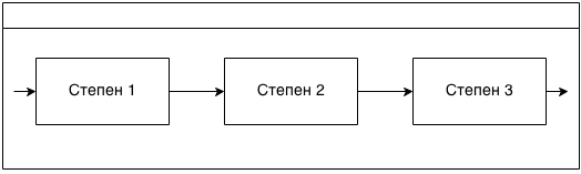
The highest priority to memory access have 3-rd stage, next is 2-nd stage and with lowest priority is 1-st stage. Fig. 6 Flowchart instruction pipeline with 2 parallel working 1-st stages 
Fig. 7 Flowchart the whole CPU. 
|